38 Results
View results:
Sort by:

Both the determination of natural vibrations and the response spectrum analysis are always performed on a linear system. If nonlinearities exist in the system, they are linearized and thus not taken into account. They are caused by, for example, tension members, nonlinear supports, or nonlinear hinges. This article shows how you can handle them in a dynamic analysis.

When a concrete slab is set upon the top flange, its effect is like a lateral support (composite construction), preventing problems of torsional buckling stability. If there is a negative distribution of the bending moment, the bottom flange is subjected to compression and the top flange is under tension. If the lateral support given by the stiffness of the web is insufficient, the angle between the bottom flange and the web intersection line is variable in this case so that there is a possibility of distortional buckling for the bottom flange.

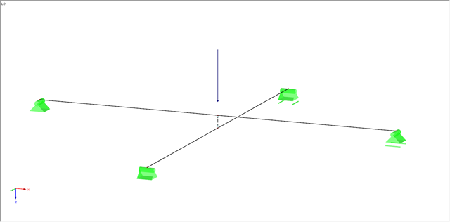
RFEM 6 includes the Form-Finding add-on to determine the equilibrium shapes of surface models subjected to tension and members subjected to axial forces. Activate this add-on in the model's Base Data and use it to find the geometric position in which the prestress of lightweight structures is in equilibrium with the existing boundary conditions.

Supports contributing to a load reduction only under compression or tension can be defined as nonlinear supports in RFEM and RSTAB. It is not always easy for the user to select the correct nonlinearity for "failure under tension" or "failure under compression".

This article deals with the determination of the concrete reinforcement for a beam stressed by tension only according to EN 1992-1-1. The aim is to show the tensile load of a member-type element (without imposed deformations) and to define the concrete reinforcement in accordance with the standard's construction rules and provisions using the RFEM structural analysis software.

The German Annex to EN 1992‑1‑1, the National Addition NCI to Article 9.2.1.2 (2), recommends to dispose the tension reinforcement in the flange plate of T‑beam cross‑sections on a maximum of one width corresponding to the half of a computed effective flange width beff,i according to Expression (5,7a).

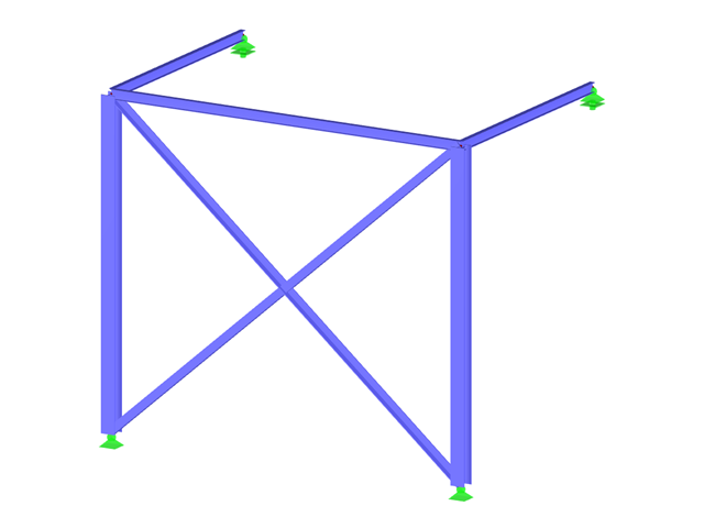
The most common causes of unstable models are failing member nonlinearities such as tension members. As the simplest example, there is a frame with supports on the column footing and moment hinges on the column head. This unstable system is stabilized by a cross bracing of tension members. In the case of load combinations with horizontal loads, the system remains stable. However, if it is loaded vertically, both tension members fail and the system becomes unstable, which causes a calculation error. You can avoid such an error by selecting the exceptional handling of failing members under "Calculate" → "Calculation Parameters" → "Global Calculation Parameters".

When connecting tension-loaded components with bolted connections, the cross-section reduction due to the bolt holes must be taken into account in the ultimate limit state design. This article describes how the design of the tension resistance according to DIN EN 1993‑1‑1 can be performed with the net cross-section area of the tension member in the RF‑/STEEL EC3 add-on module.

Concrete on its own is characterized by its compressive strength. An important part of reinforced concrete is reinforcing steel, which contributes to both the compressive and the tension resistance of the concrete. Welded wire fabric is generally located in the tension areas of the beams or surface elements (hollow core ceiling, wall, shell) to transfer the tensile forces induced by external loading.
If the calculation of a member model according to the second-order analysis is terminated with an error message, this instability is often caused by failed tension members: As soon as compressive forces appear in a tension member during a calculation step, this member is no longer considered in the following iterations. Thus, the model can become unstable.
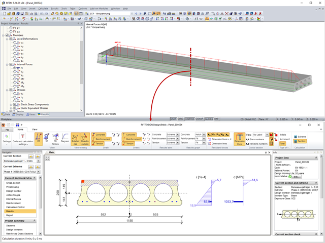
Prestressed concrete slabs consist of composite, uniaxially stressed hollow plates with a width of about 1.20 m. These elements are prestressed with pre-tension in a precast concrete plant. The precasting is usually done with slipformers. Due to the lesser self‑weight of the non‑solid slab and the existing prestress, these precast prestressed hollow core slabs show a lower deflection than loosely reinforced slabs made of solid concrete.

The previous article, titled Lateral-Torsional Buckling in Timber Construction | Examples 1, explains the practical application for determining the critical bending moment Mcrit or the critical bending stress σcrit for a bending beam's lateral buckling using simple examples. In this article, the critical bending moment is determined by considering an elastic foundation resulting from a stiffening bracing.

Both the determination of natural vibrations and the response spectrum analysis are always performed on a linear system. If nonlinearities exist in the system, they are linearized and thus not taken into account. Straight tension members are very often used in practice. This article will show how you can display them approximately correctly in a dynamic analysis.

Utilize the RF-/STEEL Cold-Formed Sections module extension to perform ultimate limit state designs of cold-formed sections according to EN 1993-1-3 and EN 1993-1-5. In addition to the cold-formed cross-sections from the cross-section database, you can design general cross-sections from SHAPE-THIN.
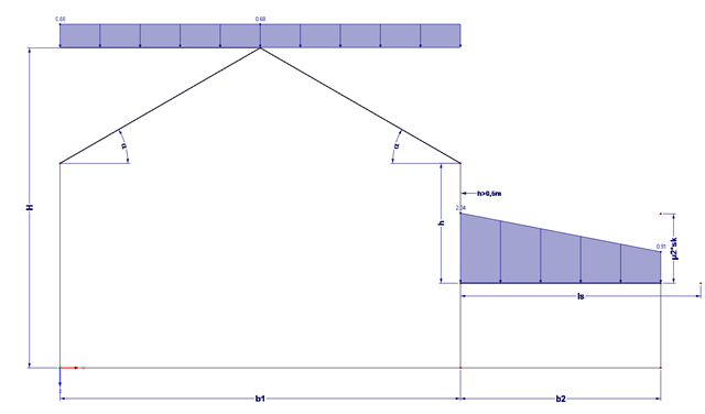
Buildings often have extensions. If the roof levels are not at the same height, this height difference (if more than 0.5 m) must additionally be considered for the snow load assumption.
Modeling planar structural components such as glass panes is generally possible only in RFEM. If it is necessary to define the stiffening effect of a pane in a particular case, it can also be simulated in RSTAB.

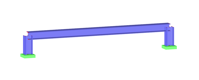
A site joint consisting of hollow sections with end plates will be designed. It is the bottom chord of a truss that has to be divided for transport reasons.

The stiffening of timber structures is usually carried out by means of timber panels. For this purpose, structural components consisting of slabs (chipboard, OSB) are connected with members. Several articles will describe the basics of this construction method and the calculation in the RFEM program. This first article describes the basic determination of the stiffnesses as well as the calculation.
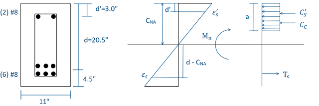
Using RF-CONCRETE Members, concrete beam design is possible according to ACI 318-14. Accurately designing concrete beam tension, compression, and shear reinforcement is important for safety considerations. The following article will confirm the reinforcement design in RF-CONCRETE Members using step-by-step analytical equations as per the ACI 318-14 standard, including moment strength, shear strength, and required reinforcement. The doubly reinforced concrete beam example analyzed includes shear reinforcement and will be designed under the ultimate limit state (ULS) design.

The design of a torsional loaded beam according to AISC Design Guide 9 will be shown, based on a verification example. The design will be performed with the RF‑STEEL AISC add-on module and the RF‑STEEL Warping Torsion module extension with 7 degrees of freedom.
From time to time, two intersecting beams overlap at a short distance. Such a structure raises the question, with regard to the modeling, of how it is possible to consider a contact with force transmission under compression between the two beams, while the contact under tension (for example, in case of a lifting top beam) should fail.
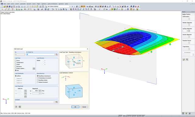
In theory, an ideal gas consists of freely moving mass particles without extension in a volume space. In this space, each particle moves at a speed in one direction. The collision of one particle with another particle or the volume limitations leads to a deflection and a change in the speed of the particles.

According to Clause 7.3.2 (2), standard DIN EN 1992-1-1 requires: "In profiled cross‑sections like T‑beams and box girders, the minimum reinforcement should be determined for the individual parts of the section (webs, flanges)." In the case of a floor beam with a T‑section, the minimum reinforcement should be determined for both flanges and the web if the corresponding partial cross‑sections are in the tension area. Image 01 shows the division into partial cross-sections.
Buildings must be designed and dimensioned in the way that both vertical and horizontal loads are conducted safely and without large deformations in the building. Examples of horizontal loads are wind, unintentional inclination, earthquake, and a blast.
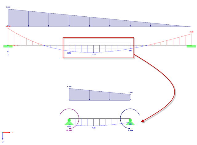
This article explains how to determine loads on the basis of the internal force situations defined in the RF‑/STEEL Warping Torsion extension of the RF‑/STEEL EC3 add-on module. Since this new program also allows you to analyze extracted chain-like beam structures in addition to entire chain-like beam structures, it is necessary to determine the loads of the partial structure separately. To do this, a special transformation function has been developed that determines new loads of all partial structures (depending on the internal forces calculated in RFEM/RSTAB) according to each load situation for geometrically nonlinear warping torsion analysis with seven degrees of freedom.
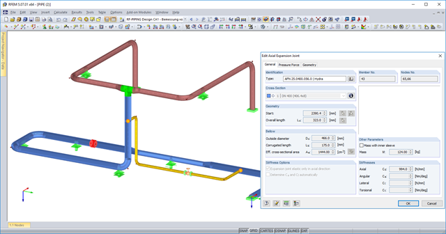
You can now use axial expansion joints in RF‑PIPING. These are applied to absorb movements of extension and compression in the axis direction due to the thermal expansions of the piping.
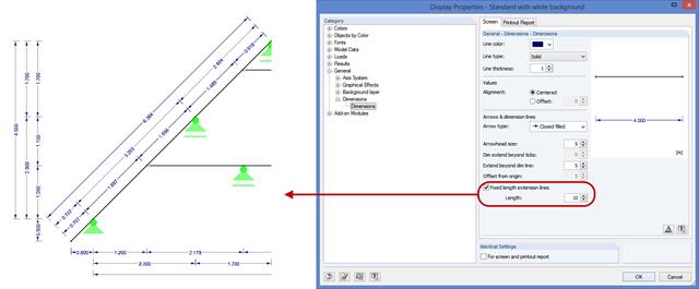
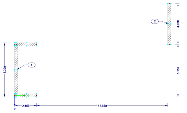
In RFEM and RSTAB, you can now define the guidelines of dimensions with a fixed length. This new option allows you to define dimensions without having the structure covered by the guidelines. This way, dimensioning is clearer. You can activate this option under "Display Properties" → "General" → "Dimensions".

In the case of tension connections with cleats subjected to unilateral loading, the external members (side timber) are loaded by an additional bending moment due to the eccentric load distribution. However, this fact is not mentioned in EN 1995‑1‑1 and is considered in the National Annex to DIN EN 1995‑1‑1 by the reduction of the tensile strength. This reduction depends on the pull-off strength of the fasteners.

The RF‑/STEEL Warping Torsion module extension of the RF‑/STEEL EC3 add‑on module allows you to design members with asymmetric cross‑sections. The new option is fully integrated in the design module and can be activated for sets of members.
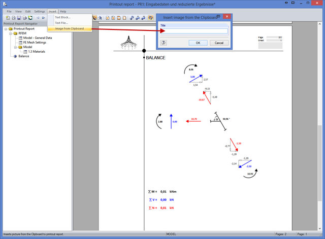
With program version x.06, you can also insert .bmp file formats from the clipboard into the printout report. Previously, only the .emf format (Windows Metafile) was supported. Thus, it is no longer necessary to insert a screenshot in a supported program (such as MS Paint) and go from there to the printout report.